| BustedGear.com |
| Shop | Repairs | Manufacturers | Resources | iFAQs | About |
|
|
|||
| Yamaha® DGX-530, YPG-535 | 2: Disassembly 2 | ||
|---|---|---|---|
|
Last Page < |
Page Bottom ∨ |
Next Page > |
|
|
|
|||
|
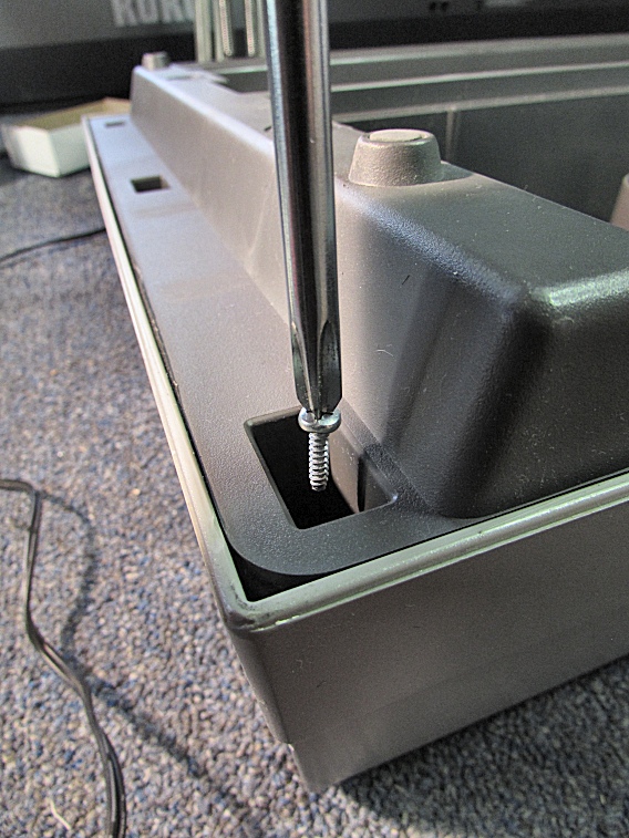
Only 20 more screws must be removed from the bottom of this Yamaha DGX-530 digital piano. These screws are in recesses around the bottom's perimeter. A magnetized screwdriver can help to reinstall the screws. There are three screws on each end of the keyboard. |
|
|---|---|
|
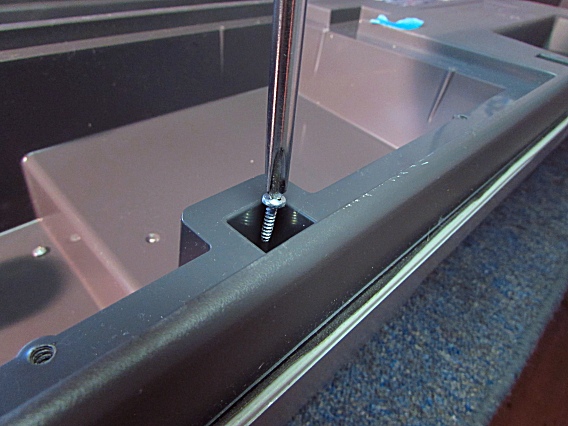
There are six screws along the rear edge. |
|
|
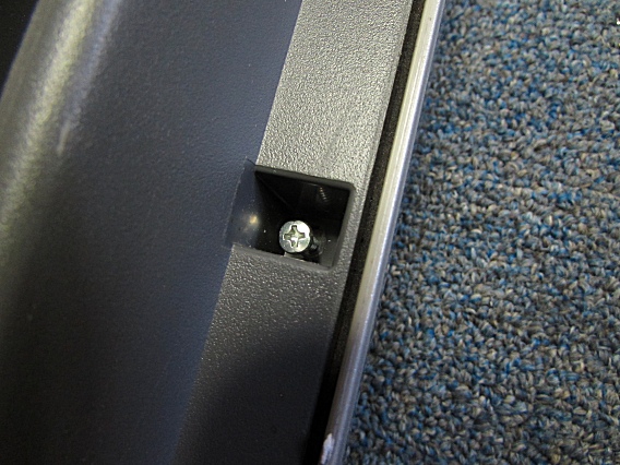
And eight screws along the front edge. |
|
|
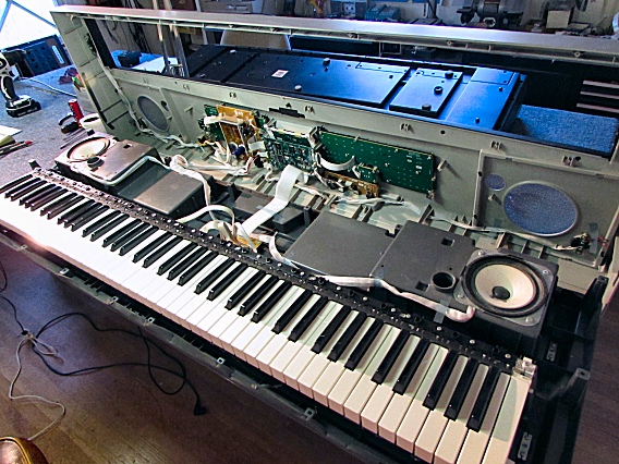
After the bottom screws are removed, you can turn the unit right side up and separate the top assembly from the bottom assembly as shown here. |
|
|
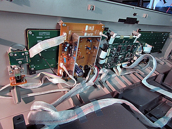
Attached to the underside of the top panel are several printed circuit board assemblies (PCBAs). |
|
|
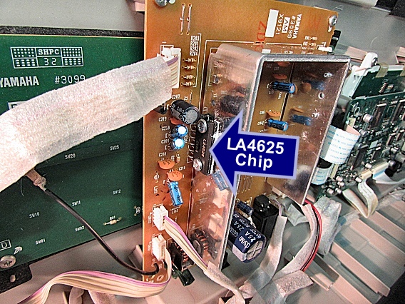
This is the "AM" PCBA, containing the instrument's power supply and audio power amp. The audio power amp resides in a 14-pin, LA4625 integrated circuit (see right). Our oscilloscope showed that there was signal on this chip's input pin but not on its output pin. To remove and install parts on this board, we have to access its foil side. |
|
| Yamaha® DGX-530, YPG-535 | ||
|---|---|---|
|
Last Page < |
Page Top ∧ |
Next Page > |
|
|
|
|
|
Page design and content Copyright © Richard Diemer - All rights reserved |