| BustedGear.com |
| Shop | Repairs | Manufacturers | Resources | iFAQs | About |
|
|
|||
| Kurzweil® PC88 | 4: Replacing Tactile Switches | ||
|---|---|---|---|
|
Last Page < |
Page Bottom ∨ |
Next Page > |
|
|
|
|||
|
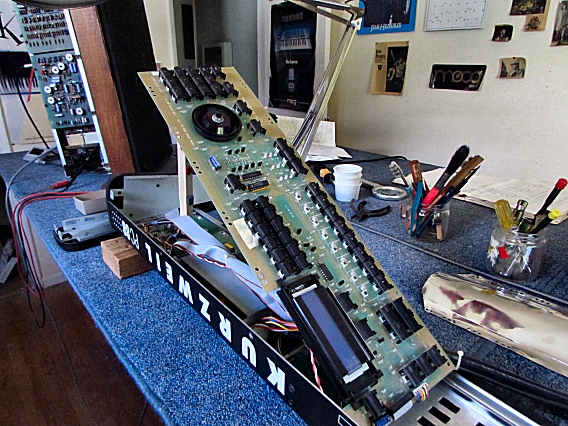
With its mounting screws removed, you can swing the PC88's panel board away from the top panel, as seen here. No cables need unplugging. |
|
|---|---|
|
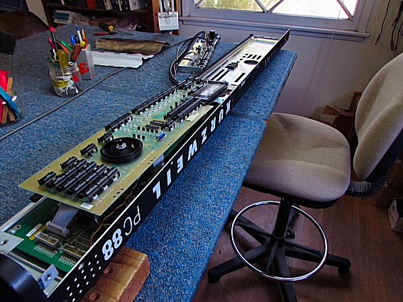
Now you can access both sides of the circuit board. |
|
|
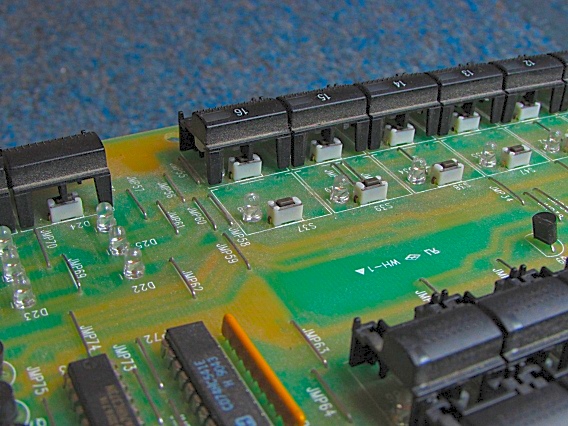
This photo shows how the panel buttons push on tiny tactile switches underneath. |
|
|
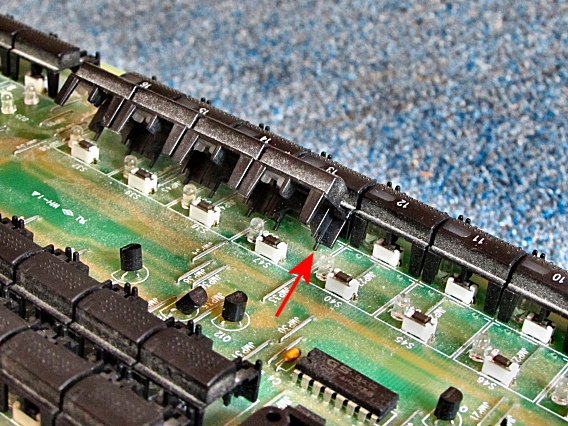
The buttons are kept in place by small pins (right) that poke through holes in the panel board . |
|
|
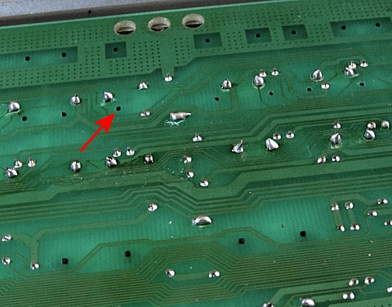
To detach a group of buttons, use a small tool to push on each of its pins from the foil side of the circuit board This photo highlights one of the pinholes. After detaching the buttons, you're ready to de-solder, remove and replace the bad switches. It doesn't matter which of the two switch leads goes to which solder point. Replacement switches for the Kurzweil PC88 |
|
|
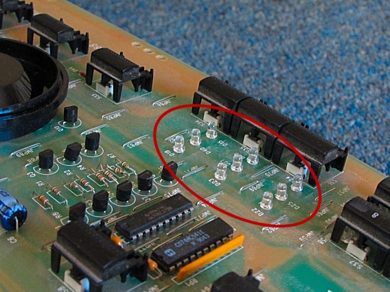
After replacing the bad switches and reinstalling the button-groups, you're ready to remount the PC Board. First, take note of the 3x3 LED matrix circled in this photo. |
|
|
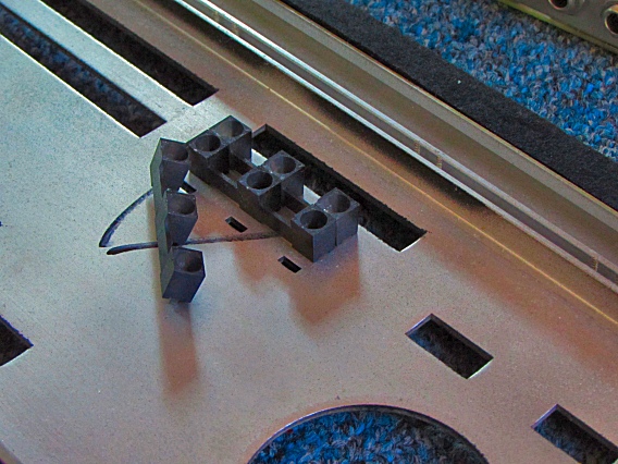
Those nine LEDs fit into the guides seen here. The guides may have fallen out and must be installed as shown. If the flat sides are facing the wrong way, the circuit board won't install properly. The board must lay flat against the mounting rails and all the buttons must fall freely into their panel cut-outs. When everything is seated, cover the boards with the foil and reinstall the screws. When remounting the jacks chassis, refer to the last page to see how the cables run over the white foil but under the silver foil. |
|
| Kurzweil® PC88 | ||
|---|---|---|
|
Last Page < |
Page Top ∧ |
Next Page > |
|
|
|
|
|
Page design and content Copyright © Richard Diemer - All rights reserved |