Prelude:
The Dance of
Charge & Magnetism
|
Flowing electric
charge and magnetic
fields interact in two ways:
-
When electric
current flows, a
magnetic field is created.
-
When a magnetic field fluctuates, an electric
voltage is created.
An inductor is a circuit component that's engineered to create
a specific amount of magnetic field—and hence voltage induction—in
either itself (self induction) or in a nearby circuit (mutual induction).
|
Let's look at the magnetic fields created by various
electric currents.
Current In A Wire
|
The magnetic field of a current-carrying wire is illustrated below.
The yellow disc is the cross section of a wire whose current flows into
the page (the "X" represents the tail of an arrow).
Magnetic "field lines" circulate around the current in a direction called north (N) to south (S).
RIGHT HAND RULE :
Point your right thumb in the direction of the electric current. Your fingers will curl in the
direction of the field.
NOTE : Keep in mind that, by convention, electric current flows from positive to
negative, opposite to the flow of electrons.
|
Current In A Ring
|
The magnetic field of a current-carrying loop or ring of wire is illustrated below.
The "X" marks where current is flowing into the page and the "•"
marks where current is flowing out of the page (the "•"
represents the head of an arrow).
Use the Right Hand Rule to reveal an interesting thing :
|
The field created by the current at the "X" and
the field created by the current at the "•" are directionally aligned
and squeezed inside the ring, increasing the overall
flux density (symbol B).
|
Current In A Coil
|
Finally, look at the magnetic field created by a current-carrying coil
of wire having many
loops or turns:
|
The flux density is further multiplied, looking much like that of a
bar magnet. Fluctuations in coil current will now induce even
higher voltages.
NOTE :
An Induced voltage is sometimes called an electromotive force, or emf (symbolℰ).
But, despite it's name, emf isn't a force. Rather, it's the potential
energy, in volts, of an electrical source when it's not producing current.
|
Faraday's Law of Induction
|
Michael Faraday discovered the law of induction in England in 1871.
In 1872, Joseph Henry discovered the law independently in America.
Faraday's Law says that the emf generated by a loop of current is equal
to the rate of change of the
magnetic flux (symbol Phi Φ)
inside the loop :
|
|
[1]
|
Where:
ℰ = the induced emf, in volts
Φ = the magnetic flux inside the loop, in webers
∆ Φ ⁄ ∆ t = the change in magnetic flux per change in time
Take note of the fact that a sudden or high-frequency flux change
will induce
a larger emf than a slow or low-frequency change.
The faster the flux changes, the more emf is generated.
For a tightly wound coil composed of N identical turns,
each with the same flux, Faraday's Law also says that:
|
|
|
[2]
|
Where:
N = the number of turns
|
Lenz's Law
|
The minus sign in Faraday's Law is called Lenz's Law in honor of
Heinrich Emil Lenz who formulated the law way back in 1834.
Lenz's Law states that any electric current induced by a change in
magnetic flux will always induce a polar opposite magnetic flux
acting against the
change.
So, when the electric current through a coil accelerates, a "back emf"
is induced,
acting against the acceleration.
And when the electric current through a coil decelerates, a "forward emf"
is induced, acting against the deceleration.

Each action generates an opposing reaction that tends to preserve the
status quo.
|
Inductance (L)
|
Coils are rated using a scale of
inductance, symbol L for
Lenz. Inductance is in henrys, abbreviated ‘H’ for
Henry.
Inductance is defined to be the ratio of the amount of flux Φ
generated by a coil to the amount of current I
flowing through the coil :
|
|
[3]
|
So, an inductor that generates one weber of flux per ampere of
current has an inductance of one henry (1 H).
Now, substitute Φ = LI into Faraday's Law
[1] as follows :
|
|
[4]
|
This shows that, if a coil's inductance (L) doesn't change, the
coil will induce a voltage equal to its inductance times the rate of
change of current :
|
|
[5]
|
Where:
V = the induced voltage, in volts
L = the inductance of the coil, in henrys
∆ I ⁄ ∆ t = the current change per
time change,
in amps / second
So, an emf of 1 V is generated by a 1 H coil when the current through
the coil changes by
1 A / s.
|
Inductors for Tone Control
|
Faraday's Law [1] says
that quick changes in magnetic flux induce more opposing voltage than do slow changes.
In other words, inductors block higher frequency tones more than lower
ones, an effect opposite to that of
capacitors, which block the lower tones more.
Note that an inductor wired in series with a circuit has
an opposite tonal effect to
the same inductor wired in parallel with the circuit :

Series-Wired Inductor
This guitar will sound bassy because only lower frequencies can
go through the coil to the speaker.

Parallel-Wired Inductor
This guitar will sound trebly because lower frequencies can go through the
coil instead of the speaker.
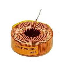
|
Ampeg® SVT
Inductor Coils
|
The following coils control tone in Ampeg®
'Super Vacuum Tube' bass guitar amps.
Since the coils are used to mold slow, bass-frequency tones, the
coils' size and inductance must be fairly large.
So, to make the SVT coils more compact, they're bent into toroidal (donut) shapes.
This coil sculpts the tone of a mid-1990's Ampeg SVT-CL
bass guitar amp.
This is the equivalent coil in an original SVT amp from the late
1960's.
|
Power Supply Chokes
|
Inductors are often used in amplifier power supplies, following the AC to DC rectification. These
so-called filter chokes smooth out pulsating direct current by
storing and releasing magnetic energy.
This 4 henry choke fits the Fender® Deluxe-Reverb and Vibrolux-Reverb guitar amps.
It also fits Fender® Hot-Rod and Blues Deluxes and
DeVilles.
|
Guitar Pickups
|
Guitar pickups use inductance to generate an electric signal from a
magnetic signal.
The magnetic signal comes from a
magnetically permeable
guitar string vibrating over the pole of a permanent magnet :
Guitar String Pickup
The permanent magnet magnetizes a length of the guitar string and, as
the string vibrates, its shifting magnetic flux cuts across a
pickup coil.
In keeping with Faraday's Law [1], an
alternating voltage ℰ is induced
in the pickup coil, mimicking the string's motion. This signal
voltage is passed to any
connected gear :
Guitar Pickup Connected to Voltmeter
|
As expected, the extremes of voltage occur when the magnetized string is moving most
quickly.
|
Transformers
|
A transformer is a device using mutual induction
to step up or down AC voltages, or to transfer signals between
circuits having
differing impedances, for example from a microphone to a mic preamp or from
a vacuum tube to a speaker.
In a transformer, two or more coils are wound around a mutual,
permeable core that directs magnetic flux from a primary
winding to one or more secondary windings.
A Simple Transformer Core
|
Alternating current in the primary winding creates an alternating
magnetic flux in the transformer core which induces an alternating
voltage In the secondary winding.
According to
Faraday's Law for coils
[2], the ratio of the secondary voltage (Vs)
to the primary voltage (Vp) is :
|
|
[6]
|
But since the flux change (ΔΦ/Δt)
is common to both coils, it cancels out of equation [6]. The voltage
ratio is simply equal to the ratio of the number of turns in the coils :
|
|
[7]
|
Therefore, the secondary voltage equals the primary
voltage times the turns ratio :
|
|
[8]
|
REMINDER: Vs and Vp are
alternating (AC)
voltages. Although a steady (DC) voltage will produce a steady
current and therefore a steady flux
in the core, a steady flux causes no
voltage induction.
This 100W output transformer fits a Marshall® JMP amp.
The primary coil (white and black wires) is center-tapped (red wire) for
the amp's push-pull
output tubes.
The 16Ω secondary coil has 8Ω & 4Ω taps.
This power-supply transformer fits the Fender® Pro Reverb,
Super Reverb, and Bandmaster Reverb guitar amps.
Its primary coil (white and black wires) connects to the AC house current.
Various AC voltages are induced in several secondary coils, powering the amp's
pilot lamp, its tube heaters, and its DC rectifiers.
|
|