| BustedGear.com |
| Shop | Repairs | Manufacturers | Resources | iFAQs | About |
|
|
|||
| Ampeg® SVT Classic | 1: Chassis Cables | ||
|---|---|---|---|
|
Last Page < |
Page Bottom ∨ |
Next Page > |
|
|
|
|||
|
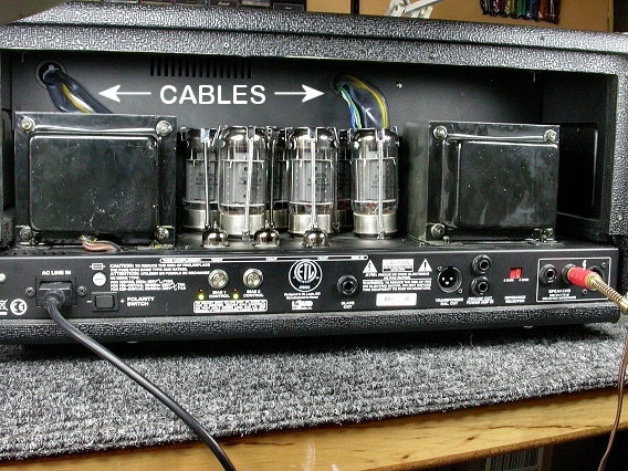
First, remove the rear screen. It's held on with black wood screws. Then, notice two cable bundles that connect the power amp chassis to the preamp chassis. The first task is to remove the preamp chassis and unplug the inter-connecting wires and cables. |
|
|---|---|
|
To remove the preamp chassis, unscrew the 4 machine screws on the top of the SVT head, shown here. |

|
|
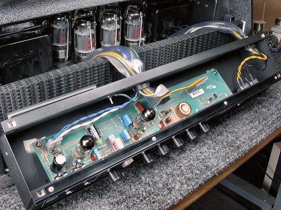
Then slide out the preamp chassis. The smaller wire bundle goes to the power and standby switches. The big cable bundle goes to various connectors on the preamp circuit board. |
|
|
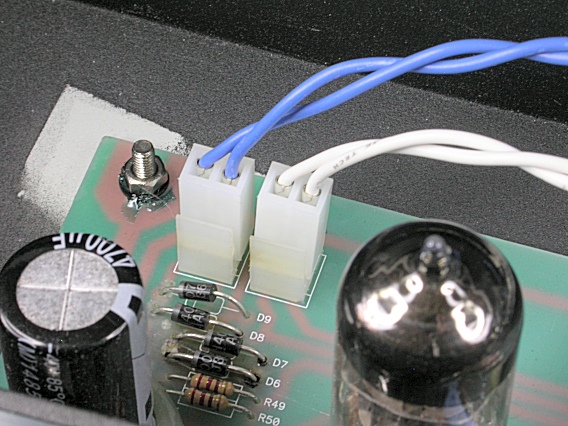
On the left end of the board, there are two connector housings with locking ramps. Spread apart the ramps and unplug them. Always keep track of which plug goes where. |
|
|
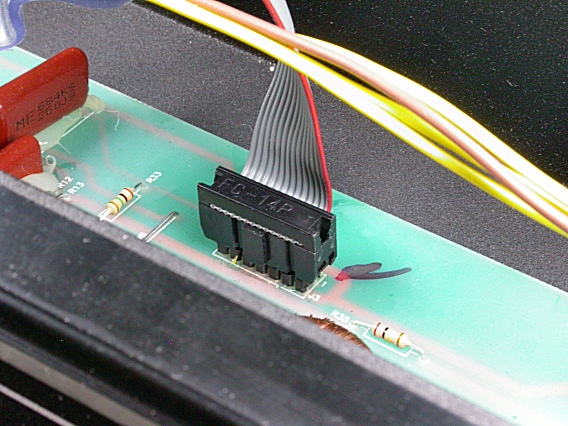
In the middle of the board, there's a 14-pin ribbon cable with a DIP (Dual Inline Package) plug. Pull straight up on the plug to separate it from the socket. Mark the corner where pin 1, the red wire, goes. |
|
|
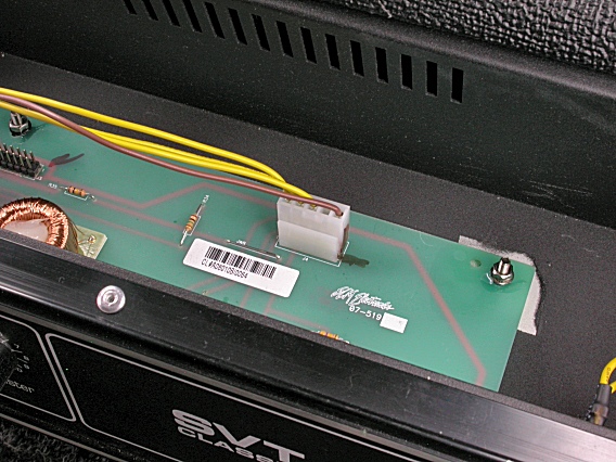
On the right end of the board is one more connector with a locking ramp. |
|
| Ampeg® SVT Classic | ||
|---|---|---|
|
Last Page < |
Page Top ∧ |
Next Page > |
|
|
|
|
|
Page design and content Copyright © Richard Diemer - All rights reserved |