| BustedGear.com |
| Shop | Repairs | Manufacturers | Resources | iFAQs | About |
|
|
|||
| Farfisa® Mini-Compact | 3: Oscillator - Divider Boards | ||
|---|---|---|---|
|
Last Page < |
Page Bottom ∨ |
Next Page > |
|
|
|
|||
|
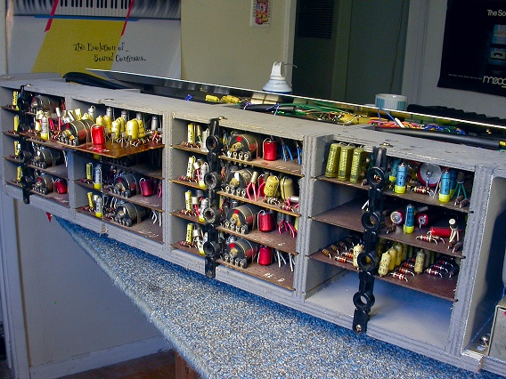
This is a rear view of the Mini-Compact's chassis. On the left, you see 3 stacks of 4 circuit boards each. These are the oscillator-divider boards. Each board generates one of the 12 highest frequencies and divides it down into its lower octaves. |
|
|---|---|
|
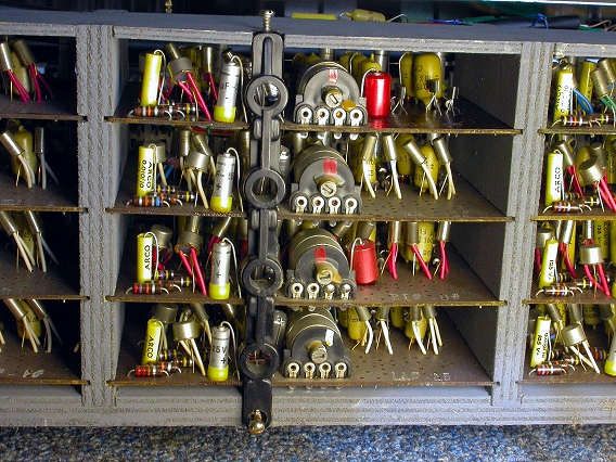
A plastic retainer keeps the boards from sliding out of grooves in the plywood. Remove the two wood screws holding the retainer to the frame. |
|
|
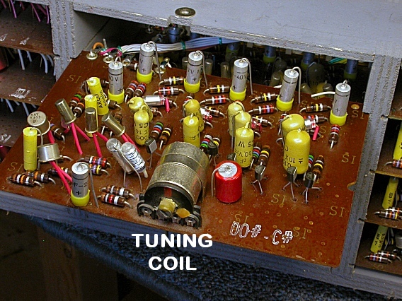
Then, slide out the board. In this case, we had a problem with the C#'s. Notice the tuning coil. It lets you control the pitch of the C#'s by screwing a ferrite slug into and out of the coil's core. This changes the coil's electromagnetic impedance. Adjustments should be made with care. The slugs and coils are fragile, and a wax sealant is used to hold the slugs in place. |
|
|
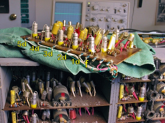
The attached wires are long enough to allow easy access to both sides of the board. Six octaves of C#'s are output via solder lugs along the edge of the board, as shown here. The top C# is labeled f and the lower octaves are labeled 1d through 5d. |
|
|
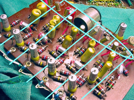
Behind the tuning coil is a row of ten transistors, shown circled here. One pair of transistors is used in each of the board's five, divide-by-two circuits. |
|
|
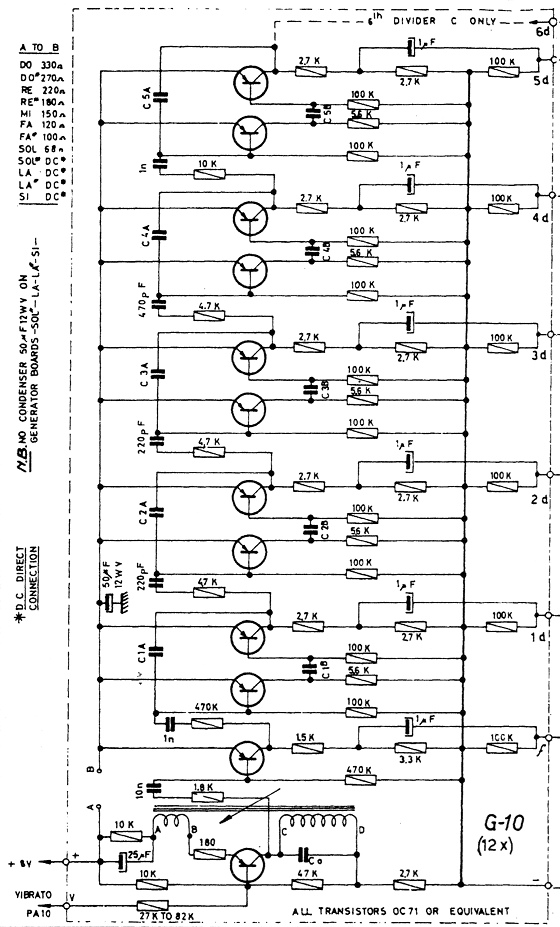
This is the schematic for one of the 12 oscillator-divider boards. The complete service manual is here: Farfisa Mini-Compact Service Manual. |
|
| Farfisa® Mini-Compact | ||
|---|---|---|
|
Last Page < |
Page Top ∧ |
Next Page > |
|
|
|
|
|
Page design and content Copyright © Richard Diemer - All rights reserved |