| BustedGear.com |
| Shop | Repairs | Manufacturers | Resources | iFAQs | About |
|
|
|||
| Fender® Hot Rod Deville | 1: Disassembly | ||
|---|---|---|---|
|
Last Page < |
Page Bottom ∨ |
Next Page > |
|
|
|
|||
|
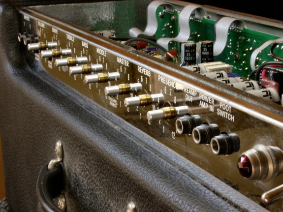
To begin work on the Fender Hot Rod DeVille, unplug the amp from the wall socket and remove the cabinet's back panel. Next, lay the amp flat on its front as shown here. Take off all the control knobs - set screws hold them onto the metal potentiometer shafts. Then, remove the hex nuts and washers fastening the pots and jacks to the top panel. It's best to use nut drivers for this:
• 7/16" for the pot nuts, |
|
|---|---|
|
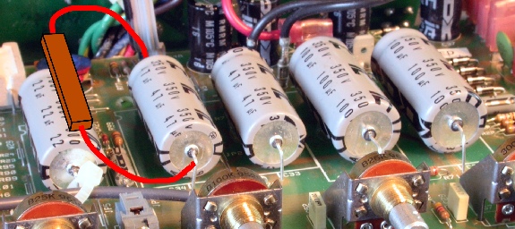
Now discharge the power supply filter capacitors of any deadly charge. They're the five gray cylinders shown here. Use insulated jumpers (alligator or mini-hook) to attach a 5 or 10 ohm, 5 or 10 watt resistor across each filter cap for 5 or 10 seconds. Clip the jumper leads to the capacitor leads, as depicted in this photo. |
|
|
There are six black screws attaching the main Printed Circuit board to the chassis. Remove them. Then detach the ground lug (below) that bolts to the chassis by the input jack. 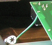
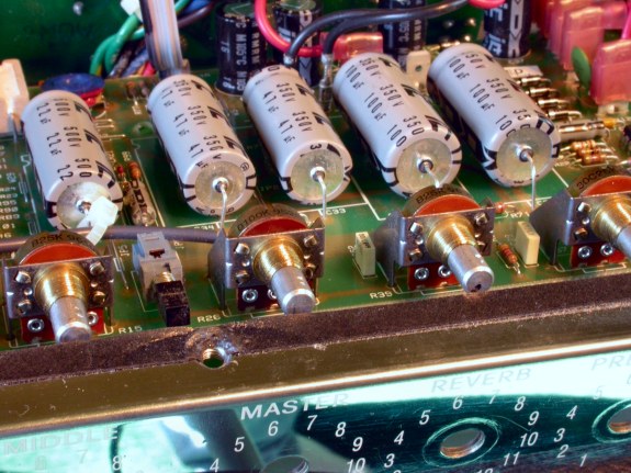
Now you can wiggle the circuit board back from the front panel. It must move back enough for the pot shafts to clear the top flange (right). |
|
|
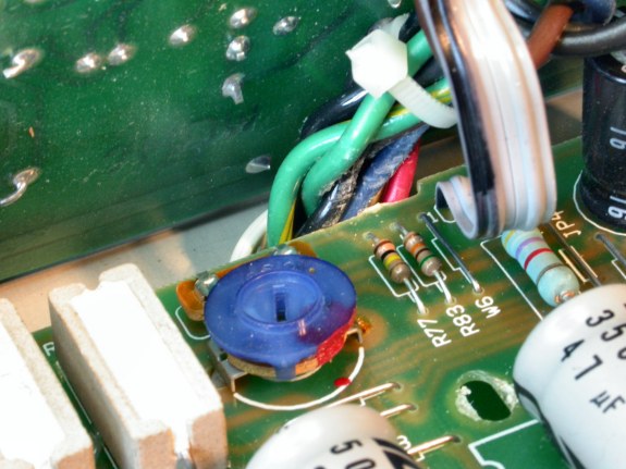
As you move the circuit board back, it will crunch up against transformer wires in the rear. Put pressure on these wires, not on the front-panel pots. To make more room, arrange the transformer wires into a single row. They'll still get scraped but it's superficial. |
|
|
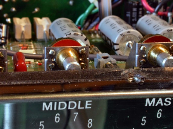
Here you see how tightly the pot shafts will clear the top flange of the top panel. Be careful not to bend the potentiometers. |
|
|
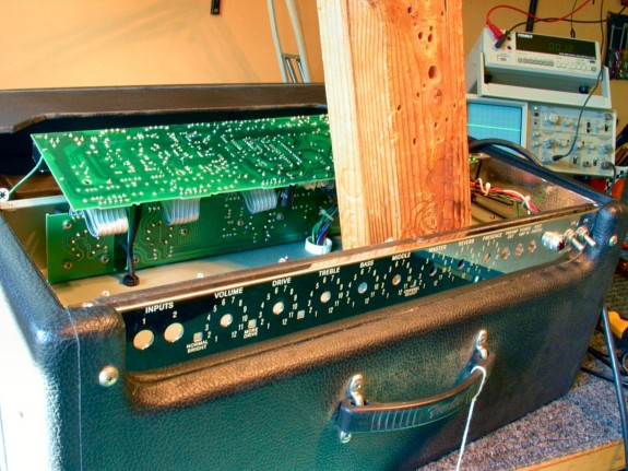
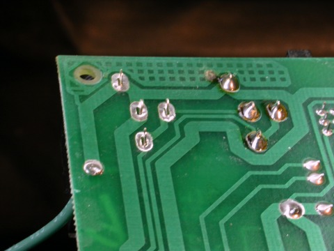
Once over that hurdle, it's easy to swing up the PC board and work on its foil side. Find a way to prop up the board in a serviceable position. 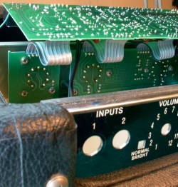
|
|
|
Desolder and remove the old jack, pop in a new jack, and solder it in place. |
|
|
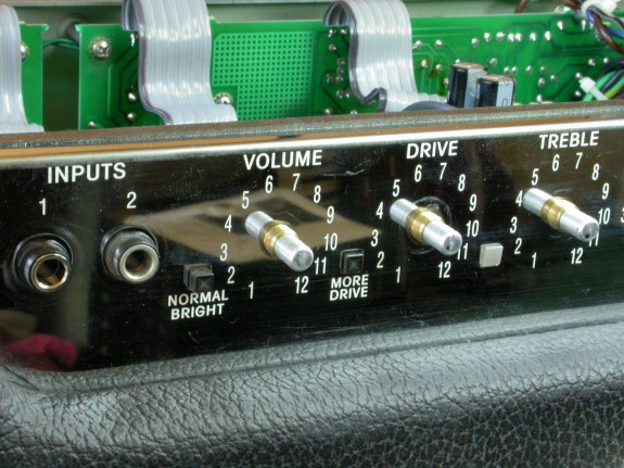
When reinstalling the circuit board, pay special attention to the Drive LED because it gets out of position very easily. Also watch the push-button switches. All the control pots must be flush against the inside of the top panel or else the push switches will be difficult to un-push. Attach the control nuts and washers first. Then put in the black, PC board screws. |
|
| Fender® Hot Rod Deville | ||
|---|---|---|
|
Last Page < |
Page Top ∧ |
Next Page > |
|
|
|
|
|
Page design and content Copyright © Richard Diemer - All rights reserved |