|
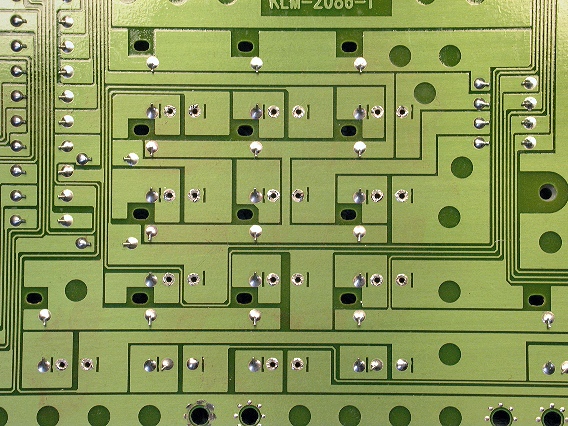
This photo shows the numeric keypad section of the Triton's Right
Button
board.
The tactile switches for 0-9 and ENTER have been removed
and their foil circuit pads cleaned.
|
|
|
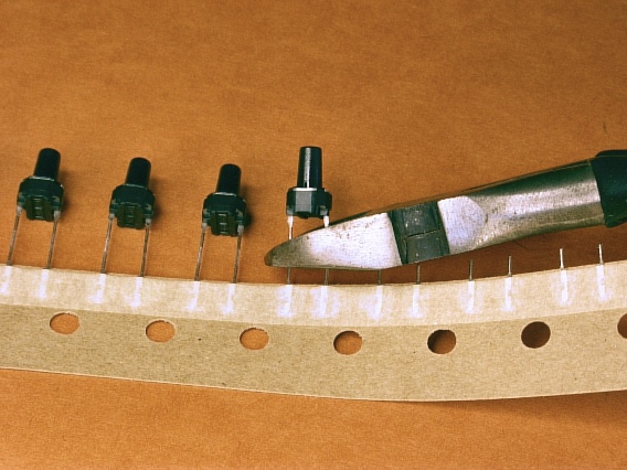
These replacement tactile switches are tape-and-reel packaged. Cut the
switches from the tape with a wire cutters as shown here.
NOTE: These tactile switches are available in our store:
|
|
|
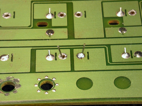
Insert the switch leads into their donut holes. It doesn't matter which lead goes
into which hole.
Then bend the leads outward a
bit. This prevents the switch from falling out when the board is
upside down.
Solder one of the switch leads to its solder pad, as shown here.
|
|
|
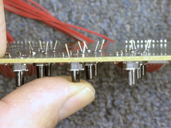
Then, push up on the switch from below and re-melt the solder,
making sure the switch body is flat against the circuit board.
Then, solder the second switch lead to its solder pad.
Lastly, cut off the excess switch leads with a wire cutters.
|
|
|
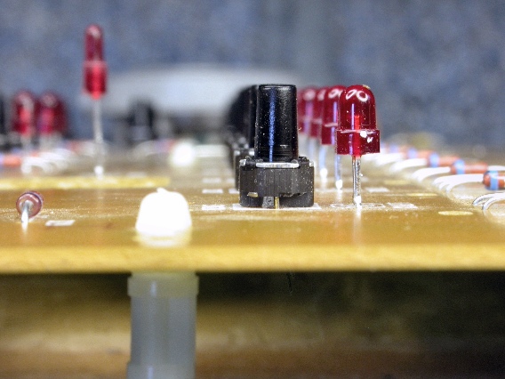
After installing tactile switches, sight along the rows and columns to make
sure the switch bodies are flat, with their stems straight up and down.
Also make sure no LED has bent away from vertical
|
|
|
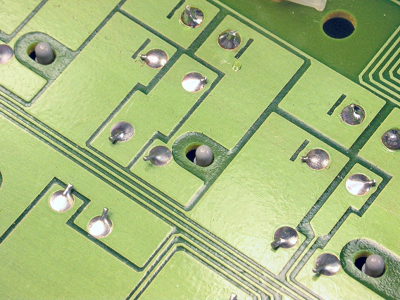
When reinstalling the Button boards, be sure the pips on the knob blocks
are fully seated in their corresponding holes in the circuit boards, as shown
here.
|
|


