| BustedGear.com |
| Shop | Repairs | Manufacturers | Resources | iFAQs | About |
|
|
|||
| Korg® Triton Pro | 3: CPU Cage Removal | ||
|---|---|---|---|
|
Last Page < |
Page Bottom ∨ |
Next Page > |
|
|
|
|||
|
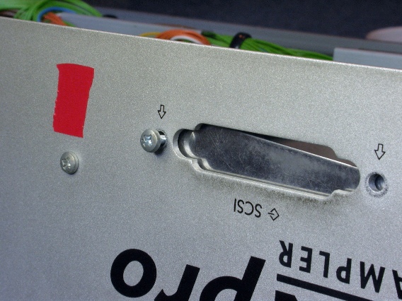
To finish releasing the computer cage, take out the screws holding it to the rear panel. This includes the screws that attach the SCSI port cover, shown here, or else the SCSI board if that is installed. |
|
|---|---|
|
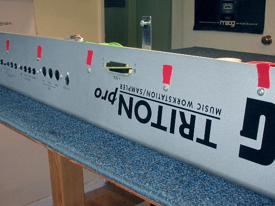
Also take out the five rear-panel screws marked in this photo. |
|
|
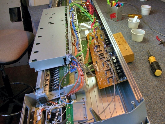
Now you can swing the computer cage away from the main chassis. Underneath you see the Analog board (the brown one) and the left and right button boards (the green ones). |
|
|
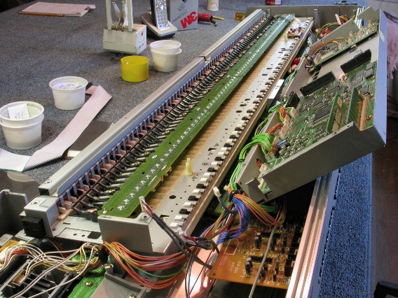
Swing the cage into this position to reveal the keyboard assembly. We'll remove the keyboard assembly next. |
|
|
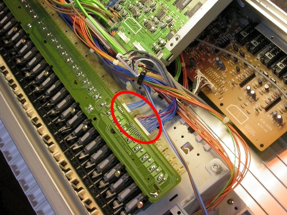
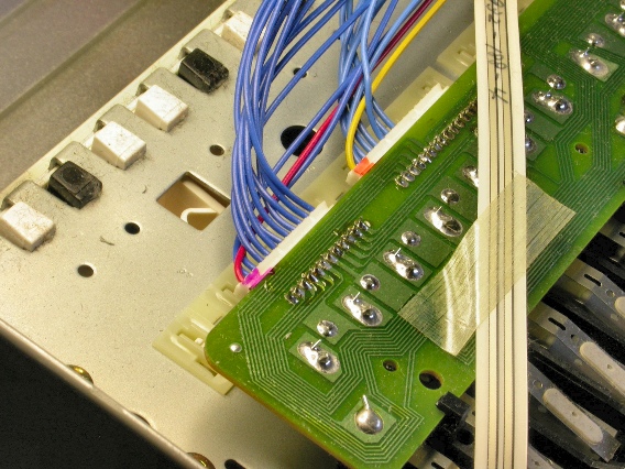
Before removing the keyboard assembly, there are connectors to unplug, including two on the left-hand end of the keyboard and two on the right. This photo shows the two connectors on the left-hand end of the keyboard assembly. |
|
|
This photo shows the two connectors on the right-hand end of the keyboard assembly. |
|
| Korg® Triton Pro | ||
|---|---|---|
|
Last Page < |
Page Top ∧ |
Next Page > |
|
|
|
|
|
Page design and content Copyright © Richard Diemer - All rights reserved |