| BustedGear.com |
| Shop | Repairs | Manufacturers | Resources | iFAQs | About |
|
|
|||
| Marshall® DSL100 | 1: Jack PC Board & Output Transformer Removal | ||
|---|---|---|---|
|
Last Page < |
Page Bottom ∨ |
Next Page > |
|
|
|
|||
|
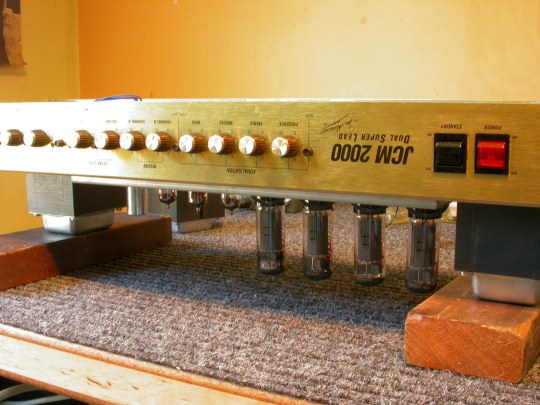
The JCM2000-series "Dual Super Lead" amplifier comes as a 50-Watt "DSL50" or a 100-Watt "DSL100" (right). There are 4 pre-amp tubes with twist-off tube shields and 4 large power tubes (or 2 in the 50-Watt version). Remove the tubes before beginning work. Grab power tubes by their plastic base, not by the glass. As you push down on the spring tube retainer with one hand, wiggle the tube from its socket with the other. In addition, discharge the power supply filter capacitors to rid them of any deadly electric charge. |
|
|---|---|
|
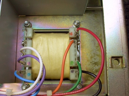
Here you see the underside of the Output Transformer (the OT). It's the transformer farthest from the On/Off switch. The transformer closest to the On/Off switch is the Power Transformer. Use a small needle-nose pliers to gently rock and pull each colored wire off its terminal lug. Use Sharpies® to color-code the lugs in case you want to reuse the transformer. The O.T. unbolts from the chassis with the aid of a screwdriver and a nut driver or pliers. |
|
|
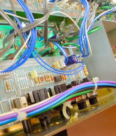
To install a power-supply choke, we have to access the Tube PC board. This means first detaching the Jack PC board from the rear panel (right). To remove this board, unscrew the plastic jack-nuts from the rear-panel jacks. A pliers works best. Cut the nylon cable ties holding the O.T. wires to the rear panel. Then back out the PC board. Install new cable ties when you reassemble the amp. |
|
|
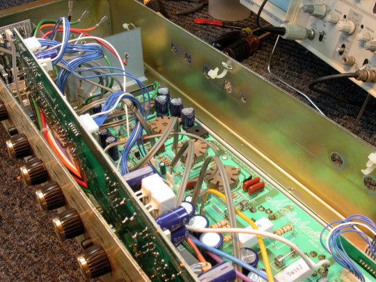
On the right, you see the Jack board swung into a vertical position against the front panel, exposing the Tube board. You see the cut cable ties on the rear panel. Unplug all the cables connecting to the Jack board. Color-code the connectors so it's easy to reconnect them. 

For example, the blue stripe on the cable header (above left) connects to the blue stripe on the PC header (above right). |
|
|
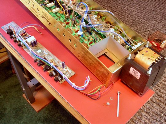
Use a needle-nose pliers to disconnect these wires. Put a matching colored dot by each lug to identify it. Now take the Jack board and the O.T. wires completely out of the chassis (right). Next, work begins on the Tube PC Board. |
|
| Marshall® DSL100 | ||
|---|---|---|
|
Last Page < |
Page Top ∧ |
Next Page > |
|
|
|
|
|
Page design and content Copyright © Richard Diemer - All rights reserved |
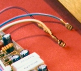 Three O.T. wires (violet, blue, and
white) push onto spade lugs on the Tube board.