| BustedGear.com |
| Shop | Repairs | Manufacturers | Resources | iFAQs | About |
|
|
|||
| Marshall® DSL100 | 2: Tube Socket PC Board | ||
|---|---|---|---|
|
Last Page < |
Page Bottom ∨ |
Next Page > |
|
|
|
|||
|
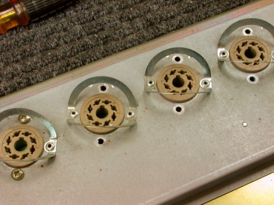
To work on the underside of the Marshall DSL100's Tube PC board, the board must be detached from the metal chassis. First, remove two brass screws beside each of the power-tube sockets. In this photo, six of the eight screws have been removed. |
|
|---|---|
|
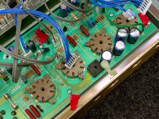
On the inside of the chassis, remove six silver screws holding down the PC board. In this photo, red tape points out three of the six PC-board mounting screws. |
|
|
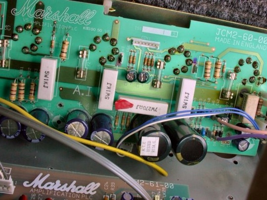
The Tube PC board is now loose. You needn't disconnect every cable from it, just enough to flip over the PC board. In this photo, red tape marks the 7-Watt, 270-Ohm resistor that will be replaced by the new choke. The resistor is designated as either R63 or R71. |
|
|
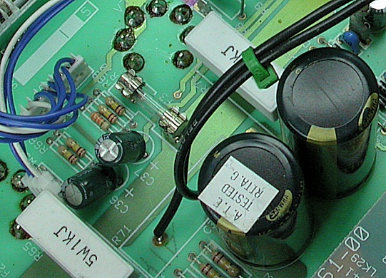
Here, R71 has been desoldered and removed. Wire leads have been soldered in its place. People will sometimes snip out parts like R71 instead of desoldering and soldering them from below. This isn't usually a great idea. |
|
|
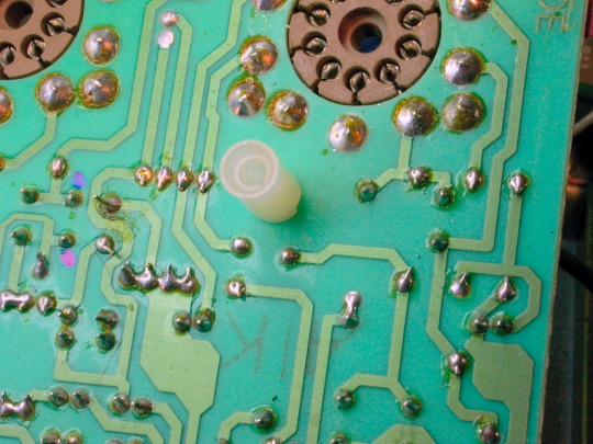
That's because there's unseen solder on the board's other side, as seen here. When soldering from above, this solder can drip downward, leaving a weak connection or shorting out to the chassis. After installing the wire leads, it's time to continue with the choke installation. |
|
| Marshall® DSL100 | ||
|---|---|---|
|
Last Page < |
Page Top ∧ |
Next Page > |
|
|
|
|
|
Page design and content Copyright © Richard Diemer - All rights reserved |