| BustedGear.com |
| Shop | Repairs | Manufacturers | Resources | iFAQs | About |
|
|
|||
| Moog® Micromoog | 2: Contour Generator Repair | ||
|---|---|---|---|
|
Last Page < |
Page Bottom ∨ |
Next Page > |
|
|
|
|||
|
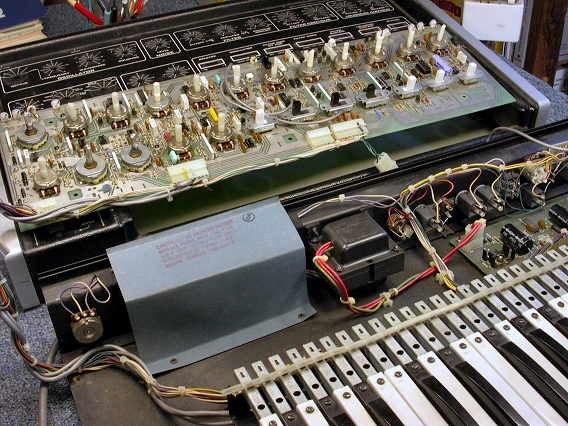
With the Micromoog's intermittent issues cleaned up, it's time see if its loudness and filter contours are working. In this photo, the main pcb is reconnected to the wiring harness and output jack. The mod wheel is still disconnected, but the synth is turned on and sounding. Placing the board on the control panel makes it easy to identify the pots and switches while you troubleshoot the board. |
|
|---|---|
|
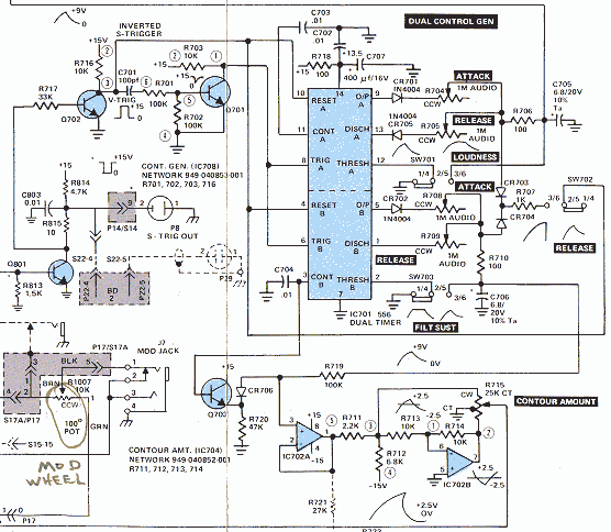
The contours were still not working so it was time to pull out the schematic. The Micromoog's Dual Contour Generator is based on the common "556" dual-timer IC. It's the large blue rectangle in the schematic to the right. Oscilloscope probes of the IC inputs and outputs verified that neither timer in the 556 was working.
|
|
|
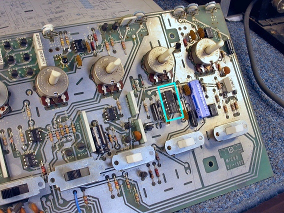
Here, you can see the timer chip, on the right side of the board. |
|
|
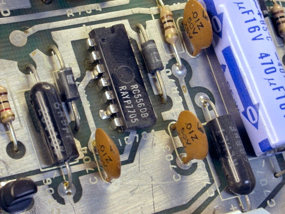
The printing on the chip shows that it was made by Raytheon, during the 5th week of 1977. The chip needs to be snipped off the circuit board and replaced with a socket. |
|
|
Here, in place of the chip, you see the newly installed 14-pin IC socket. For detailed photos of how to remove a soldered-in IC and install a socket, view our IC Socketing Repair Story |
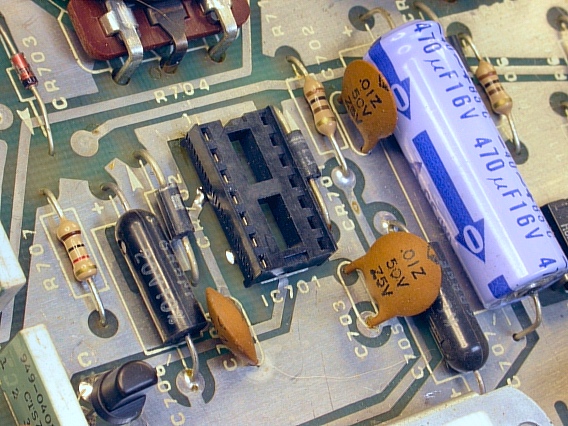
|
|
Here's the new integrated circuit, the heart of the Micromoog's dual contour generator. Because we installed a socket, the chip will be easy to replace if it ever fails. This 556 was manufactured by Fairchild Semiconductor in the 49th week of 1983. |
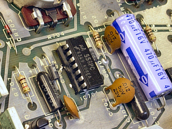
|
|
After cleaning, repairing, reconnecting, and powering up the main board, a rectifier diode in the Micromoog's power supply burned out, taking the two power supply fuses with it. The diode, a 1N4004, was replaced, two new, 1/8 amp, slo-blo, AGC size fuses were installed (shown here) and everything was fine. |
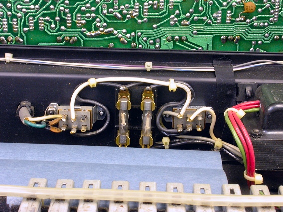
|
| Moog® Micromoog | ||
|---|---|---|
|
Last Page < |
Page Top ∧ |
Next Page > |
|
|
|
|
|
Page design and content Copyright © Richard Diemer - All rights reserved |