| BustedGear.com |
| Shop | Repairs | Manufacturers | Resources | iFAQs | About |
|
|
|||
| Peavey® 6505+ | 1: Main PCBA Removal | ||
|---|---|---|---|
|
Last Page < |
Page Bottom ∨ |
Next Page > |
|
|
|
|||
|
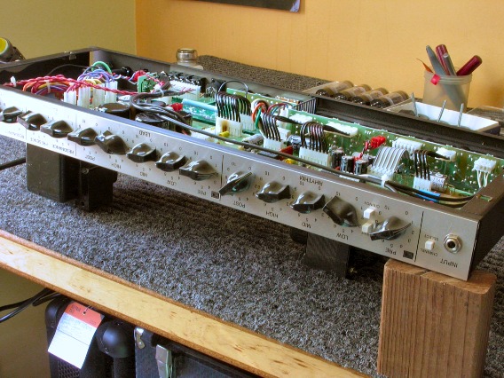
To remove the Peavey 6505+ chassis, first take out four black woodscrews that hold on the rear screen. Then take out four long machine screws that attach the feet and bolt the chassis to the cabinet. With those screws removed, the chassis pulls out for examination, as seen here. |

|
|---|---|
|
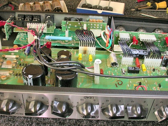
The main Printed Circuit Board Assembly (PCBA) is in front. The output tubes' PCBA is rear-left; the preamp tubes' is rear-right. Already a problem can be seen. |

|
|
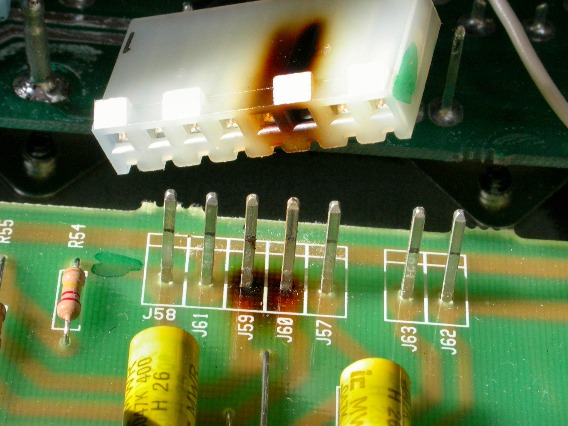
There's a short circuit between two pins of an 8-pin cable. Current can leak through the burned section of the nylon header. These two pins (J59 and J60) run filament voltage from the main PCBA to the output tubes. The short circuit prevents the output tubes from heating up and working. The result is no speaker output. Three of the four power tubes were also bad in this amp. A tube failure might have caused a spike exceeding this connector's tolerance. |

|
|
Unplugging the cable reveals that the circuit board itself is burned. Simply installing a new interconnect cable will not fix the short circuit. The burned part of both the cable header and the circuit board must be isolated. That means the main PCBA must be removed from the 6505+ chassis. |

|
|
Take off all the front-panel control knobs and remove the control-pot nuts, as shown here. The pot nuts use a 9mm driver. The nut on the input jack uses a 1/2" driver. You can also use pliers to remove the nuts. |

|
|
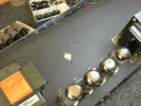
On the underside of the chassis, remove 9 black machine screws securing the PCBA. In this photo, one of the screws is marked with a piece of masking tape. |

|
| Peavey® 6505+ | ||
|---|---|---|
|
Last Page < |
Page Top ∧ |
Next Page > |
|
|
|
|
|
Page design and content Copyright © Richard Diemer - All rights reserved |