| BustedGear.com |
| Shop | Repairs | Manufacturers | Resources | iFAQs | About |
|
|
|||
| Peavey® 6505+ | 3: Short Circuit Fix | ||
|---|---|---|---|
|
Last Page < |
Page Bottom ∨ |
Next Page > |
|
|
|
|||
|
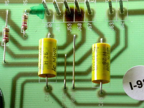
With the PCBA removed, we get a close-up look at the printed circuit foil feeding pins J59 and J60. We want to reroute filament current around the damaged section of the printed circuit board. The board's brown color indicates that its material is burned, letting electric current leak from one foil trace to the adjacent one. |
|
|---|---|
|
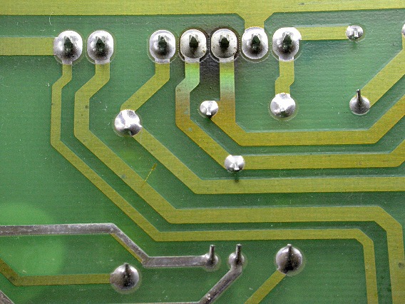
This photo shows the foil on the underside of the board. The discoloration of the copper foil is another sign of damage. |
|
|
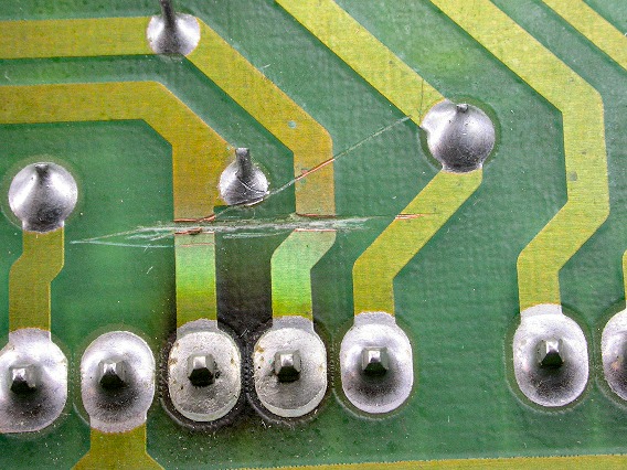
Use a pen knife to isolate the foil under the damaged section of the board. |
|
|
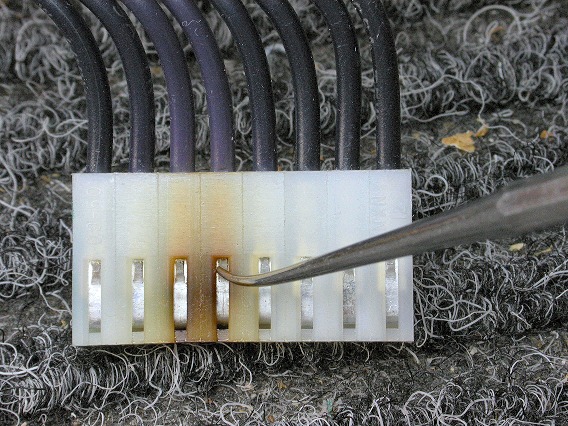
The cable header damage must also be isolated. Rather than just snipping the two wires where they enter the header, I'm going to pull out the spring contacts. It's a good skill to learn because such contacts frequently need replacing. |
|
|
The contacts lock into the header using a little one-way tab, as seen here. Use a small jewelers screwdriver, dental pick, or soldering aid to flatten the tab so you can pull the contact and wire out of the header. |
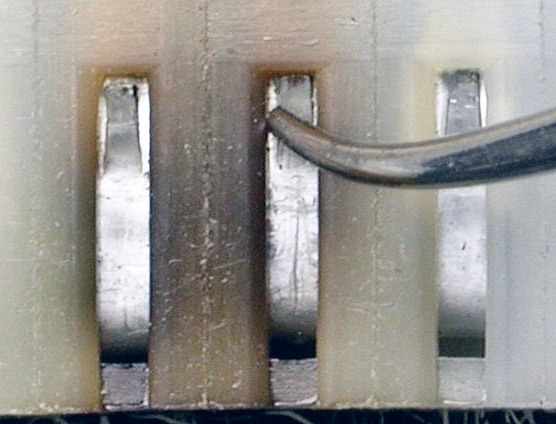
|
|
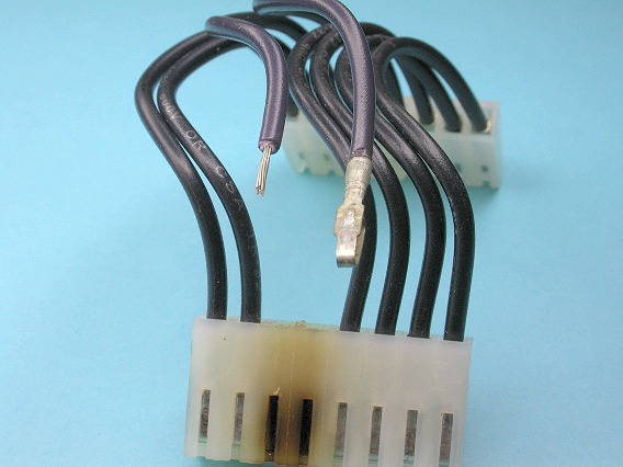
Here's the two wires released from the header. Contacts are crimped onto the wires. If you can't pull a contact off the wire, cut it off and strip 1/4" of insulation from the wire. . . . . .
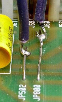
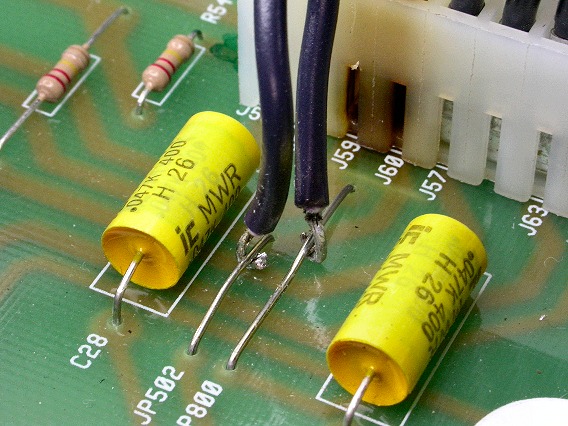
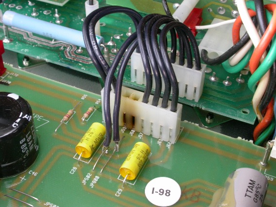
After reinstalling the repaired PCBA into the 6505+ chassis, tin the two wires and pinch them around the wire jumpers, JP502 and JP800 (see lower right). Then solder the wires to the jumpers (see below). |
|
|
|
|
The damage is now quarantined. Notice that the wire on the right (J60) goes to the jumper on the left (JP502). Refer to the photo at the top of this page to see why this is. (In truth, it doesn't matter if these two AC filament wires are reversed.) |
|
| Peavey® 6505+ | ||
|---|---|---|
|
Last Page < |
Page Top ∧ |
Next Page > |
|
|
|
|
|
Page design and content Copyright © Richard Diemer - All rights reserved |