| BustedGear.com |
| Shop | Repairs | Manufacturers | Resources | iFAQs | About |
|
|
|||
| Peavey® Classic 30 | 1: Removing the Chassis | ||
|---|---|---|---|
|
Last Page < |
Page Bottom ∨ |
Next Page > |
|
|
|
|||
|
The first step to repairing a Peavey Classic combo amp is to remove the amplifier chassis from the speaker cabinet. Four black bolts hold the chassis to the cabinet's top (this photo shows three of the bolts). Two additional bolts are on each side of the cabinet. Before removing the chassis, detach the speaker wires. The wires have spade lugs that pull off of the speaker terminals. Use two hands to prevent breakage. |

|
|---|---|
|
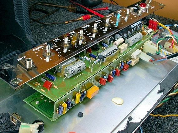
Here you see the removed chassis. Notice the 3-sided printed circuit board (pcb) assembly. The circuit board with the control pots and the power supply is parallel to the board with the vacuum tube (valve) sockets. |
|
|
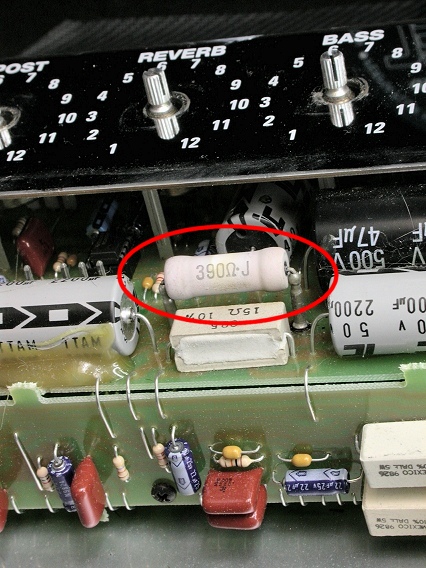
The 390 ohm resistor circled in this photo is the part we want to replace. Diagnosis showed that this resistor, which conducts current to most of the valves, was open. |
|
|
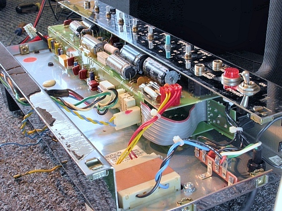
This photo shows the other end of the chassis. Next, we'll remove the pcb assembly. |
|
|
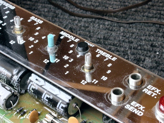
Begin by pulling off the knobs. Friction holds them onto their potentiometer shafts. Next, remove the nuts from the pot bushings and from the 1/4" jacks. The jack nuts use a 1/2" nut driver. The pot nuts use an 11/32" driver. |
|
|
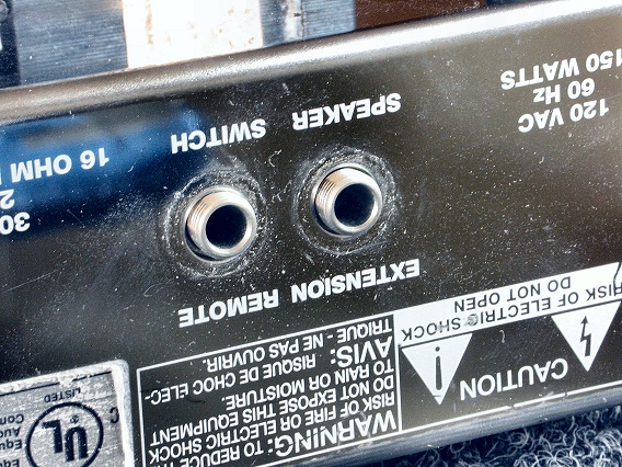
Also remove two jack nuts from the rear panel. |
|
|
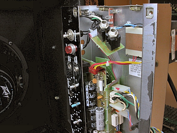
This frees the rear-panel jack board (see photo). Just leave it attached to the main circuit board assembly. |
|
| Peavey® Classic 30 | ||
|---|---|---|
|
Last Page < |
Page Top ∧ |
Next Page > |
|
|
|
|
|
Page design and content Copyright © Richard Diemer - All rights reserved |