| BustedGear.com |
| Shop | Repairs | Manufacturers | Resources | iFAQs | About |
|
|
|||
| Peavey® Classic 30 | 2: Removing the PC Boards | ||
|---|---|---|---|
|
Last Page < |
Page Bottom ∨ |
Next Page > |
|
|
|
|||
|
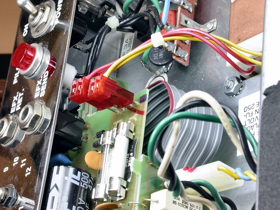
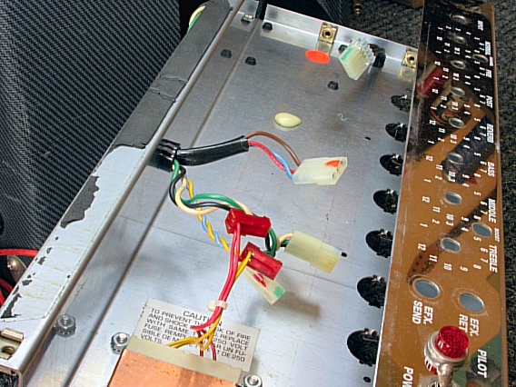
Now unplug several connectors from the Classic 30's pcb assembly. Pull off the two red connectors shown here. |
|
|---|---|
|
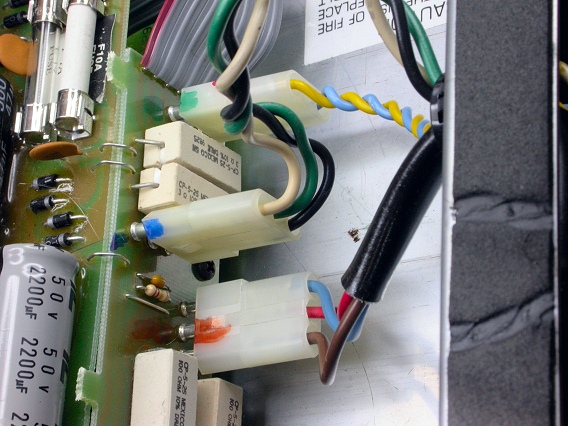
And the three Molex connectors shown here. Color coding the connectors ensures that you get them back together correctly.
|
|
|
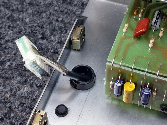
Also, pull the reverb-tank cables (right). They connect to the 4-pin header shown below. 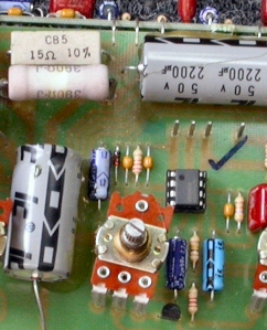
|
|
|
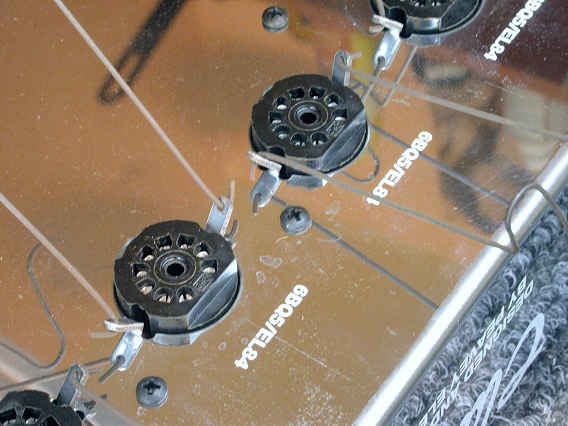
Finally, remove 8 black machine screws surrounding the valve sockets. Three of the screws are visible in this photo. Also, unhook the wire tube retainers from eyelets attached to the sockets. |
|
|
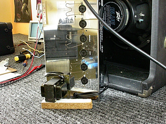
Now, it's just a matter of squeezing the pcb assembly out of the chassis. Stand the chassis on its end, as shown here, so you can push in on the valve sockets and the potentiometers at the same time. |
|
|
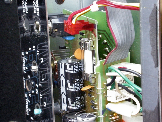
This photo shows the pot shafts receding through the holes in the control panel. It also shows the valve board pushed inward, with the sockets clear of the chassis. |
|
|
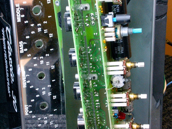
When everything's clear, the whole assembly will come out of the chassis. |
|
|
Here's the chassis with the circuit board assembly removed. |
|
| Peavey® Classic 30 | ||
|---|---|---|
|
Last Page < |
Page Top ∧ |
Next Page > |
|
|
|
|
|
Page design and content Copyright © Richard Diemer - All rights reserved |