| BustedGear.com |
| Shop | Repairs | Manufacturers | Resources | iFAQs | About |
|
|
|||
| Peavey® Classic 30 | 3: Replacing Resistor R58 | ||
|---|---|---|---|
|
Last Page < |
Page Bottom ∨ |
Next Page > |
|
|
|
|||
|
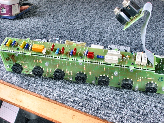
Here's the 3-sided circuit board assembly removed from the Peavey Classic 30 chassis. |
|
|---|---|
|
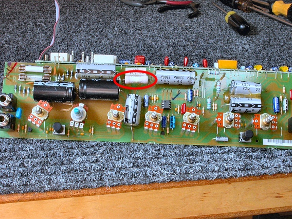
The resistor circled in this photo (R58) needs to be replaced. Diagnosis showed that this resistor, which conducts current to most of the valves, was open. |
|
|
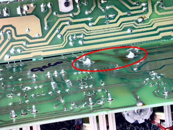
Circled here are R58's solder points on the foil side of the pot board. |
|
|
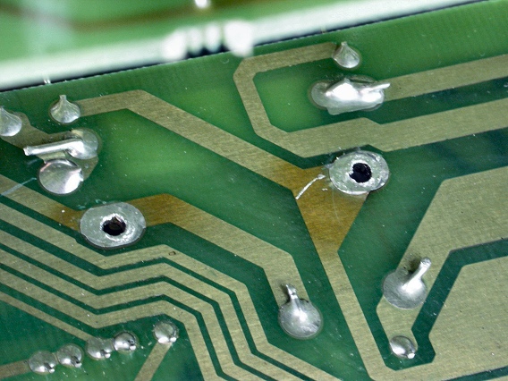
Here, the bad resistor is removed and the solder pads cleaned, using MEK and an acid brush. |
|
|
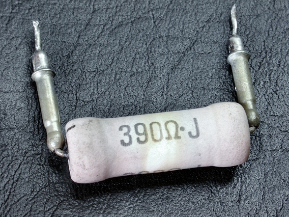
This is the original power resistor. It's rated at 7 watts and 390 ohms although the schematic calls for 400 ohms. The metal posts add stability to the resistor's leads, allowing the resistor to stand off the circuit board. The resistor gets hot and it's important for heat to dissipate into the air and not burn the circuit board material. |
|
|
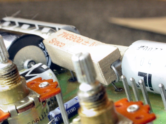
Here's the new 7 watt resistor installed in place of the bad one. It's also mounted to stand off the circuit board. Notice that the board is dark where the resistor leads pass through it. This is due to heat from too much current flowing through the old, failing resistor. The old resistor eventually burned out and could no longer conduct current to the valves. |
|
|
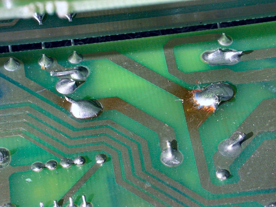
This photo shows how the new resistor leads are soldered to the circuit foil. Some extra resist was scraped off the foil near one solder pad using a razor blade or pen knife. The result is a larger, stronger connection. |
|
|
On top, RTV silicone keeps the resistor from wobbling by securing it to neighboring surfaces. Hot glue can also be used. The repair is now complete and everything can be put back together. |
|
| Peavey® Classic 30 | ||
|---|---|---|
|
Last Page < |
Page Top ∧ |
Next Page > |
|
|
|
|
|
Page design and content Copyright © Richard Diemer - All rights reserved |