| BustedGear.com |
| Shop | Repairs | Manufacturers | Resources | iFAQs | About |
|
|
|||
| Korg® 01/WFD | 3: Removing the Main Board | ||
|---|---|---|---|
|
Last Page < |
Page Bottom ∨ |
Next Page > |
|
|
|
|||
|
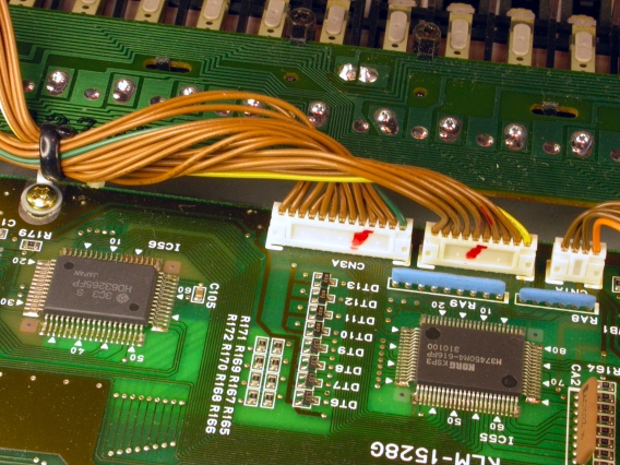
This photo shows the PCB screw at the other front corner of the 01/W's main circuit board. Take out this screw and also unplug the 3 miniature connectors seen to the right. |
|
|---|---|
|
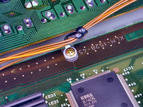
The 3rd and final PCB screw is in the middle of the board's front edge. Each of the 3 screws holds down a wire cable tie. |
|
|
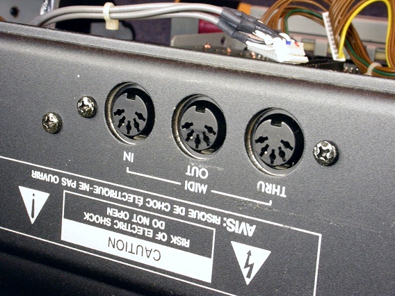
Finally, on the 01/W's rear panel, there are 6 black mounting screws you must remove. Two self-tapping screws attach to the MIDI jacks. |
|
|
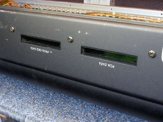
Four machine screws attach to the Printed Circuit Board Assembly (3 are seen here). |
|
|
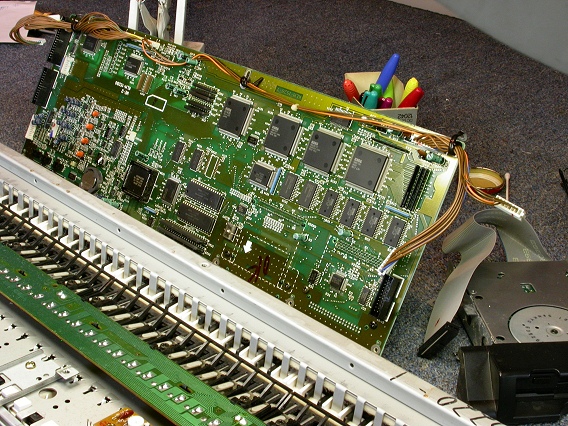
Now the main PCBA can be removed from the 01/W. |
|
| Korg® 01/WFD | ||
|---|---|---|
|
Last Page < |
Page Top ∧ |
Next Page > |
|
|
|
|
|
Page design and content Copyright © Richard Diemer - All rights reserved |