| BustedGear.com |
| Shop | Repairs | Manufacturers | Resources | iFAQs | About |
|
|
|||
| Korg® M1 | 3: Removing the Switch Board | ||
|---|---|---|---|
|
Last Page < |
Page Bottom ∨ |
Next Page > |
|
|
|
|||
|
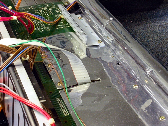
The keybed assembly is now out of the Korg M1 workstation. To access the M1's Switch circuit board, you must roll back a foil sheet. The grounded foil isolates between the Switch board and the computer boards already removed. |

|
|---|---|
|
About 15 gold screws hold down the foil. Four of the screws also hold down two more brackets. Here you see the left bracket. |
|
|
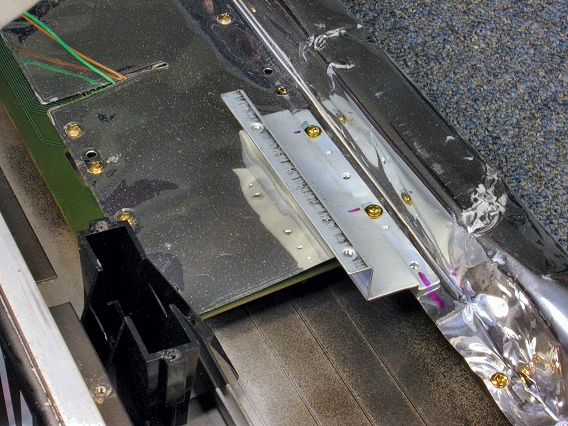
Here you see the right bracket. The bracket screws are self tapping. The others are machine screws. |
|
|
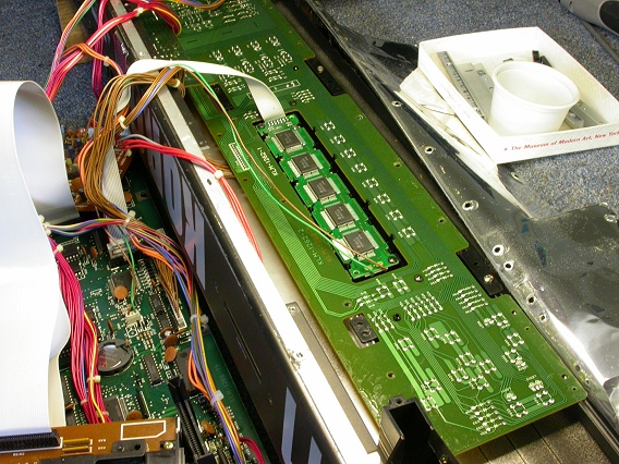
Here, the foil is rolled back and the Switch circuit board (KLM-1262) is in plain view. |
|
|
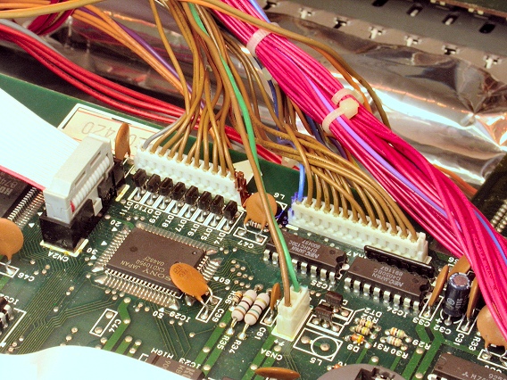
Before removing the Switch board, unplug four connectors on the CPU board. They lie within the green outline in this photo. |

|
|
This photo shows the four CPU board connectors:
|
|
|
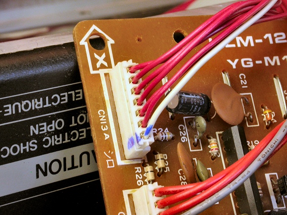
On the DAC board, unplug one connector, shown here. It's a 7-pin plug with 1 white and 6 red wires - CN13A. |
|
|
Unplug one connector to the Jack circuit board (KLM-1263). The Jack board is still attached to the M1's rear panel. This plug has 1 blue and 7 orange wires. Finally, cut a cable tie that straps the unplugged cables to the others. Replace the tie later to keep the cables neat. |

|
| Korg® M1 | ||
|---|---|---|
|
Last Page < |
Page Top ∧ |
Next Page > |
|
|
|
|
|
Page design and content Copyright © Richard Diemer - All rights reserved |