| BustedGear.com |
| Shop | Repairs | Manufacturers | Resources | iFAQs | About |
|
|
|||
| Korg® M1 | 4: Switch Buttons | ||
|---|---|---|---|
|
Last Page < |
Page Bottom ∨ |
Next Page > |
|
|
|
|||
|
Here's a photo of the Korg M1's Switch circuit board. A few more screws still attach the board to the M1's shell. Remove two black self-tap screws, one on each side of the Display board. They're marked with red tape in this photo. |

|
|---|---|
|
Also remove two gold machine screws on the left end of the circuit board, marked here. |

|
|
Now you can remove the Printed Circuit Board Assembly, seen here. |

|
|
With the PCBA removed, notice the plastic buttons that operate the tactile switches. Here you see eight buttons on the left side of the LCD Display. |

|
|
These are the buttons that operate the numeric keypad on the right of the M1's Display. As you can see, one button broke off its "button group". The button was pressed too hard because its corresponding tactile switch was worn out. The main axis of the button group can be either horizontal or vertical. Each group has to be aligned correctly. |

|
|
That's because the tactile switches aren't located under a button's center but under a tab on its perimeter. The result is the odd numeric switch pattern seen here. |

|
|
Here, the tactile switches are removed and the board is labeled with their numeric values. |

|
|
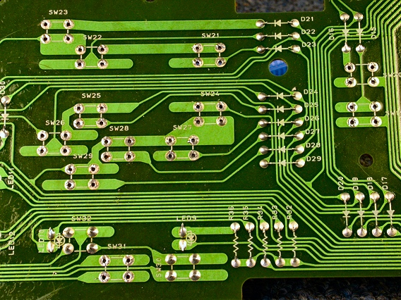
Here you see the foil side of the Switch circuit board. The Numeric, the Page Up, and the Page Down switches are removed. |

|
|
When you put the board back in, use the two black nibs (one seen here) to help you get the board back into place. You can pretty much reverse your steps to reassemble the Korg M1, using these photos if needed. When you reconnect CN2A and CN3A, pay attention to the cables' routing. And take care not to pinch any cables when reinstalling circuit boards. |

|
| Korg® M1 | ||
|---|---|---|
|
Last Page < |
Page Top ∧ |
Next Page > |
|
|
|
|
|
Page design and content Copyright © Richard Diemer - All rights reserved |