| BustedGear.com |
| Shop | Repairs | Manufacturers | Resources | iFAQs | About |
|
|
|||
| Moog® Rogue | 3: Replacing the Power Jack | ||
|---|---|---|---|
|
Last Page < |
Page Bottom ∨ |
Next Page > |
|
|
|
|||
|
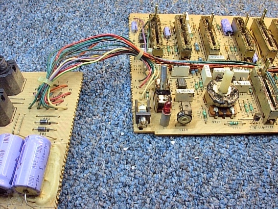
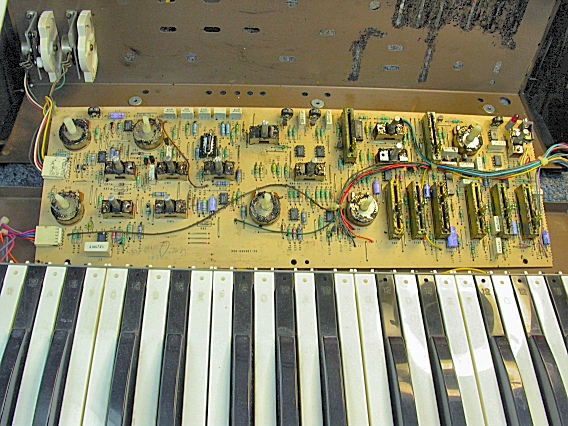
Here, the Moog Rogue's main board is cleaned and we're ready to install a new Moog Rogue power jack. |
|
|---|---|
|
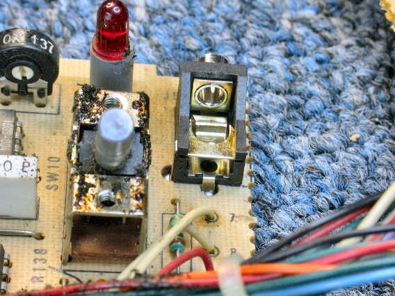
A mono 1/8" phone jack with a normally-closed tip shunt is used to input power from a 24 VAC, 200mA wall transformer. In the Rogue, there's no battery power to interrupt so the jack's tip shunt isn't used. |
|
|
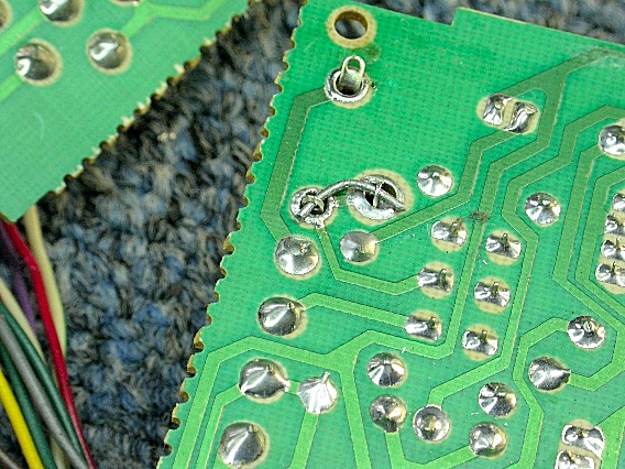
The main board's printed circuit foil already connects the jack's tip and shunt terminals but adding an extra stub of wire between the terminals adds stability to the jack. Solder holes in the terminals of the jack accommodate a solid wire brace (right). |
|
|
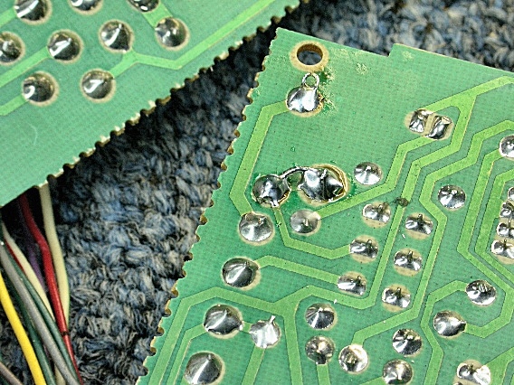
When soldering a jack, use one finger to hold it flush to the circuit board until the solder solidifies. Here, the soldering is complete and the board is ready to reinstall. |
|
|
Reconnect the cables to the wheels and the keyboard before remounting the main board. As before, set all the lever switches so their handles stick straight up (even if that's an in-between position). After installing the main board, reinstall the jacks board. |
|
| Moog® Rogue | ||
|---|---|---|
|
Last Page < |
Page Top ∧ |
Next Page > |
|
|
|
|
|
Page design and content Copyright © Richard Diemer - All rights reserved |