| BustedGear.com |
| Shop | Repairs | Manufacturers | Resources | iFAQs | About |
|
|
|||
| Yamaha® MOTIF 6 and 7 | 2: Pulling Connectors | ||
|---|---|---|---|
|
Last Page < |
Page Bottom ∨ |
Next Page > |
|
|
|
|||
|
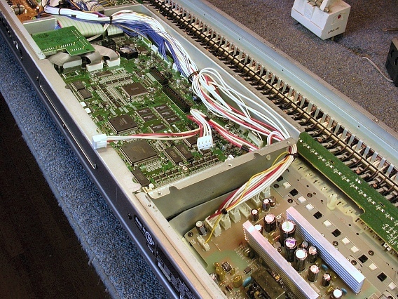
The first connectors to pull are on the Main printed circuit board assembly in the mid section of the Motif's shell. The Main board assembly mounts inside of a metal sub-chassis or cage and holds all the computer chips. To the right of the cage (in this photo) is the Power Supply Unit. To the left of the cage, and barely visible, is the Output board assembly. |
|
|---|---|
|
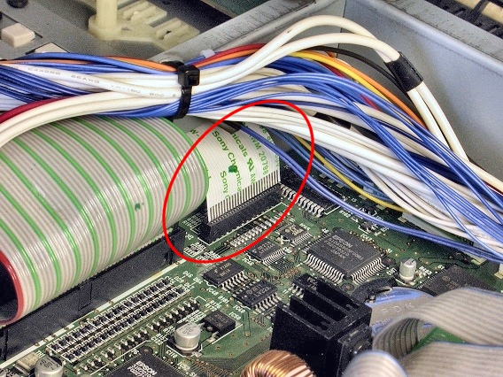
First, disconnect the Sony flexible card in the front-left corner of the Main circuit board. Push away the bundle of wires and ease the card out of its circuit board header, as shown here. |
|
|
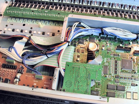
The Sony card is routed to the audio output board, as seen in this photo. |
|
|
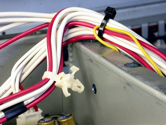
Next, pull out the push-in cable tie on the opposite end of the shielding cage. Use a pliers to pinch together its locking tabs. |
|
|
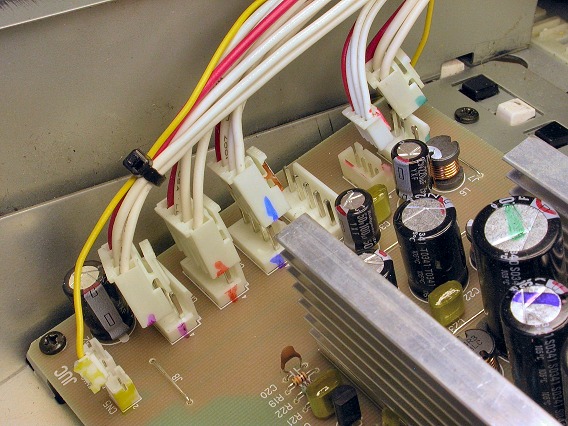
Next, pull the connectors on the left side of the power supply unit. Most of them have a release tab to push before pulling the connector from its header. Use Sharpies® to identify the connections first. This makes reconnection easier. The 5-pin header is unused. And two of the cables might go nowhere since they power up expansion boards. |
|
|
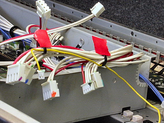
Finally, cut the two black cable ties marked with red tape in this photo. This frees the thin, yellow wire from the main cable bundle. The yellow wire powers the LCD display. Install new cable ties when reassembling the unit. |
|
| Yamaha® MOTIF 6 and 7 | ||
|---|---|---|
|
Last Page < |
Page Top ∧ |
Next Page > |
|
|
|
|
|
Page design and content Copyright © Richard Diemer - All rights reserved |