| BustedGear.com |
| Shop | Repairs | Manufacturers | Resources | iFAQs | About |
|
|
|||
| Yamaha® MOTIF 6 and 7 | 3: Main Board | ||
|---|---|---|---|
|
Last Page < |
Page Bottom ∨ |
Next Page > |
|
|
|
|||
|
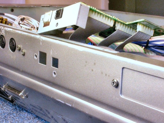
The next step in disassembling the MOTIF is to detach the USB/Optical circuit board assembly from the rear panel. Two black sheet metal screws attach the assembly to the panel, as shown is this photo. |
|
|---|---|
|
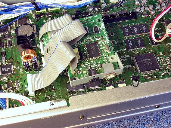
Don't unplug the USB board from the Main board. Just flip it over like this. |
|
|
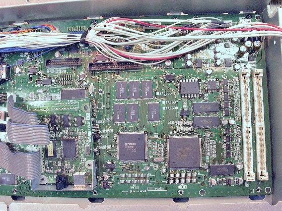
Now, free the Main circuit board assembly from its metal cage by removing 10 black mounting screws. Five of the screws are along the top of the board and five are along the bottom. (Top and bottom refer to the photo.) You can see where four screws have been removed from the bottom of this board. |
|
|
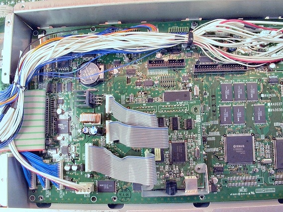
At the top of the board, push the wire bundle away from the cage's wall to reveal the screw heads. A cable clamp mounts to the third screw from the top left. Bend it into the position shown here to access the screw. Keep track of where cable clamps go. Set them aside so they don't fall off unnoticed. |
|
|
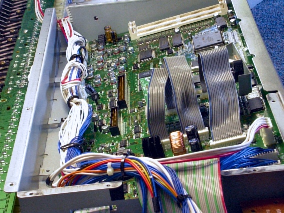
With the 10 screws removed, you can lift up the Main circuit board assembly. The edge closest to the keyboard lifts up first when removing the board and drops in last when reinstalling it. |
|
|
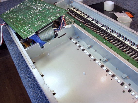
Since all the cables on the right side of the Main board are unplugged, you can pivot the whole assembly up and to the left. Rest it upside down as shown here. |
|
|
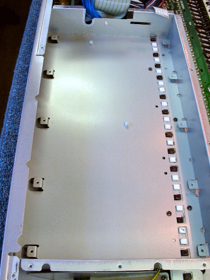
Here you see the empty shielding cage. We'll remove it next. |
|
| Yamaha® MOTIF 6 and 7 | ||
|---|---|---|
|
Last Page < |
Page Top ∧ |
Next Page > |
|
|
|
|
|
Page design and content Copyright © Richard Diemer - All rights reserved |