| BustedGear.com |
| Shop | Repairs | Manufacturers | Resources | iFAQs | About |
|
|
|||
| Korg® X3 | 2: Switch PC Board Removal | ||
|---|---|---|---|
|
Last Page < |
Page Bottom ∨ |
Next Page > |
|
|
|
|||
|
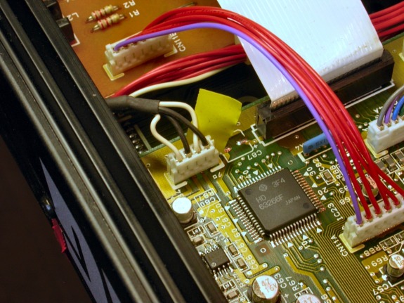
In this photo, only two cables need unplugging. One, marked with yellow tape, is like the one we unplugged on the last page. The other is the flat, card cable going to the disk drive. With two hands, ease this card out of its connector slot. |
|
|---|---|
|
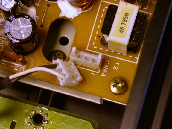
There's one more cable to unplug. It goes to a 3-pin header (right) on the Power Supply PC board.
And there's a wire bundle to unclamp from the middle mounting rail
(below).
|
|
|
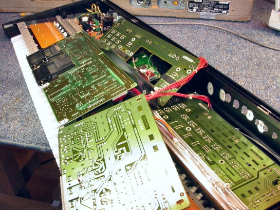
Now the Computer and Analog PC boards can be flipped over to reveal two Switch boards. The center Switch board surrounds the LCD display and is shown lifted up in this photo. Lifting it is our next goal. The other Switch board is easy to lift - just remove a few mounting screws. |
|
|
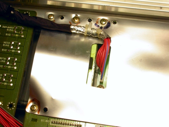
Lifting the center board is made more difficult by a foil shield between it and the Computer board and also by the LCD display and its controller. The trick with this board is keeping track of where the screws go - there are lots of extra holes in everything. |
|
|
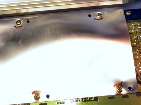
Use a Sharpie® to mark the screw positions. Note that the screws along the rear edge of the circuit board are shorter than the ones along the front edge. |
|
|
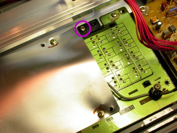
The screw circled in this photo holds down the knob block. The knob block is made of black plastic and it clips onto the Switch board. Remove the screws holding the knob block to the front mounting rail. |
|
|
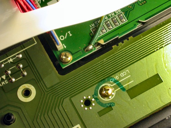
Also remove the LCD.GND screw (right). It was hiding under the shield. Don't forget to reinstall this screw before reinstalling the shield over it. At this point, you can lift up the Switch PC board and the attached knob block. |
|
| Korg® X3 | ||
|---|---|---|
|
Last Page < |
Page Top ∧ |
Next Page > |
|
|
|
|
|
Page design and content Copyright © Richard Diemer - All rights reserved |
